Drawout MCC NX Screw-Jack Type
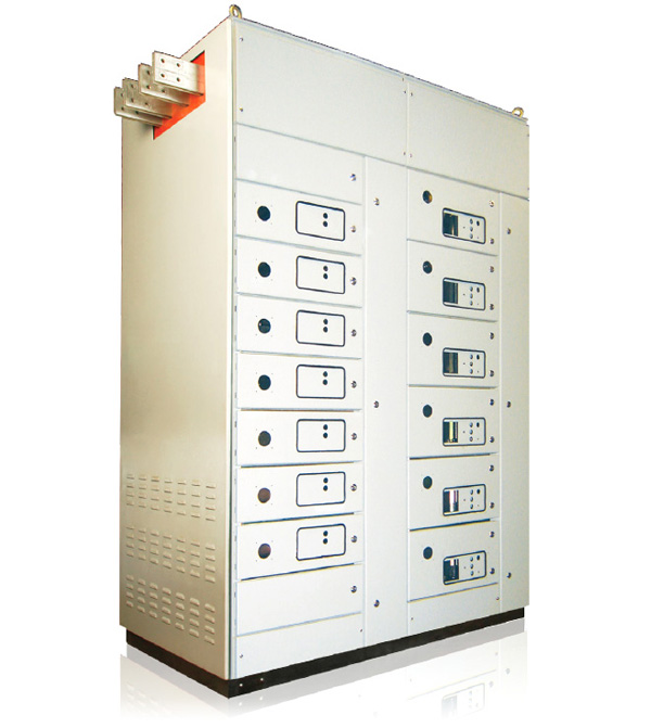
Features at a glance
- Type tested to conform to leading Global Product Standards. (IEC-61439-1 & 2).
- Fully Compartmentalized (Form IV) Design.
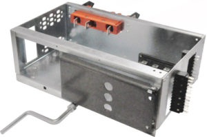
- Drawout modules have Screw-Jack mechanism for withdrawal, ensuring smooth operation.
- Drawout modules plug-in directly on to Vertical Bus Bar, minimizing maintenance issues.
- Vertical Bus is Joint-free along the feeder area, therefore is highly reliable.
- Spring Loaded positive safety shutter providing IP 20 levels of segregation upon withdrawal.
- Shock-free operation with Double Stab-in earthing in all Drawout modules.
- Fully Bolted Modular Structural design.
- Drawout Modules have position indication for Test, Service & Isolated.
- Drawout Modules available in 3 Pole for Starter feeders & 4 Pole for Power feeders.
- Drawout Module width has been increased to accommodate more material within same module height.
- Useful for reducing overall panel dimensions by making the modules stack compactly.


- Drawout Modules available in sizes from 200mm to 900mm in multiples of 100mm in height.
- Higher ratings provided using combination of two feeders with common door interlock.
- Feeder width of 585mm & depth of 250mm.
- Upto 9 feeders in one vertical stack.
- Feeder ratings upto 110kw DOL possible in 900mm.
- Max. possible feeder rating upto 150kw DOL in 1800mm.
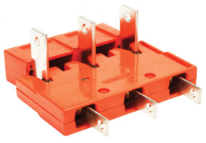
- Drawout Power & Control Contacts tested as part of Drawout Module during Full Type Test for Temperature Rise, Milli-volt Drop & other related tests in accordance with IEC-61439-1 & 2.
- Drawout Power Contact ratings:
- 63A | 125A | 250A | 400A
- Available in 1 Pole, 2 Pole, 3 Pole & 4 Pole.
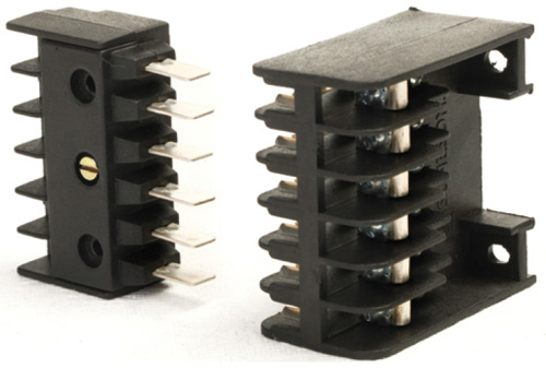
- Feeder width of 585mm with twin fully offset control terminals.
- Minimum feeder size of 200mm can accommodate 24 control terminals.
- Keeping the modules compact and making the panel space efficient.
- Drawout Control Contact ratings:
- 12A | 16A
- Available in 6-Way & 10-Way Blocks.
Specifications
| STANDARDS | IS 8623, IEC 61439 – 1&2 | ||
|---|---|---|---|
| Insulation Characteristics | Clearance | > 20 mm | |
| Creepage distances | > 20 mm | ||
| Overvoltage category | II / III / IV | ||
| Pollution degree | 3 | ||
| Field condition | Inhomogeneous (Non-uniform) | ||
| Electrical Characteristics | Voltage ratings | Rated operational voltage (U ) e | 415-690 VAC, 24-220 VDC |
| Rated insulation voltage (U ) i | 690 V | ||
| Rated impulse withstand voltage (U ) imp | 6 / 8 kV | ||
| Rated frquency (f ) n | 50 / 60 Hz | ||
| Current Ratings | Main Horizontal busbars: | ||
| Rated current (I ) nA | up to 4000 A | ||
| Rated peak withstand current (I ) pk | up to 176 kA | ||
| Rated short-time withstand current (I ) cw | up to 80 kA, 1s | ||
| Vertical Distribution busbars : | |||
| Rated current (I ) nA | 960A | ||
| Rated peak withstand current (I ) pk | up to 105 kA | ||
| Rated short-time withstand current (I ) cw | up to 50 kA, 1s | ||
| Mechanical Characteristics | Degree of protection | In accordance with IEC 60529: | |
| External | IP 4X/54 | ||
| Internal | IP 2X | ||
| Forms of separation | as per IEC 61439 – 2 | Form III/IV | |
| Dimensions | Height (mm) | 2100, 2200, 2400 | |
| Width (mm) | 600, 700, 800, 900, 1000, 1100 (ACB section) | ||
| 850 (Outgoing section) | |||
| Depth (mm) | 600, 800, 1000, 1200 (ACB section) | ||
| 600, 800, 1000, 1200 (Outgoing section) | |||
| Surface Treatment | Structure | GI-280 / powder coated / painted | |
| Internal Components | GI-280 / powder coated / painted | ||
| External Components | Powder coated / painted | ||
| Resistance to Connection | Damp heat cycling test | IEC 60068-2-30 | |
| Salt mist test | IEC 60068-2-11 | ||
| Plastic Components | Flame retardant, self-extinguishing, Halogen-free | IEC 60695-2-10, IEC 60695-2-11 | |